A new
design is in the works, please stand by
In the mean
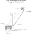
time you can check out the new arm animation courtesy of my new CAD program.
Click Here
For this project I am assuming you are a reasonable fabricator and have decent metal working tools, and a good welder. This is not a project for
the ill-equipped.
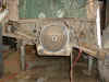
The jig is the part that takes a little creativity, and some good alignment skills. It is also the most important part of this whole thing.
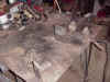
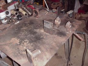
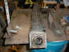
The first thing to do is to get a good stock arm and pull all of the pieces out of it. I created a grid of sorts on a piece of 1/4" plate that was about three feet square (I also use it for my lengthened/widened chromoly front arms). I created three pieces of angle about two inches wide, three inch base and four inches tall. The arm needs to be held a couple inches off of the surface for one of the arms. The arms are identical except for the shock mounts are upside-down on one of them.
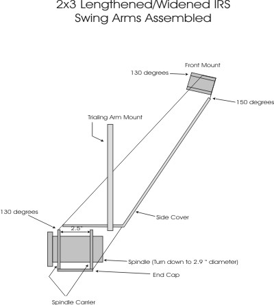
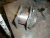
For the front mount I used a piece of round stock that I machined down to fit inside the 2" 1/4 wall tube (not to fit inside the stock arm). For the springplate I just used an angle so I could clamp the shock mount/springplate component in place. For the spindle end I machined down a bearing retainer so the surface was parallel to the bearing carrier.
I realize this is a bit vague but if there is a lot of confusion about building a jig then maybe this is not the project for you.
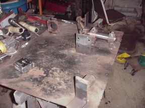
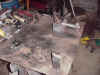
I set the stock arm up on blocks, and set up the mount points for the front and the
spring plate. Weld the mounts for both of these to the surface and mark the alignment and placement of the bearing carrier face (the side the wheel would mount to). Make sure the line for both the spring plate and the bearing carrier are parallel.
Remove the stock arm and measure the change in bearing carrier placement. To use stock bus arms, you will want two inches wider and three inches longer. Move the mount for the bearing carrier that distance and tack the angle in place. I will be making some new arms in a couple days so I will take pics of the steps and of the jig to clarify some things.
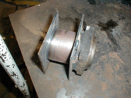
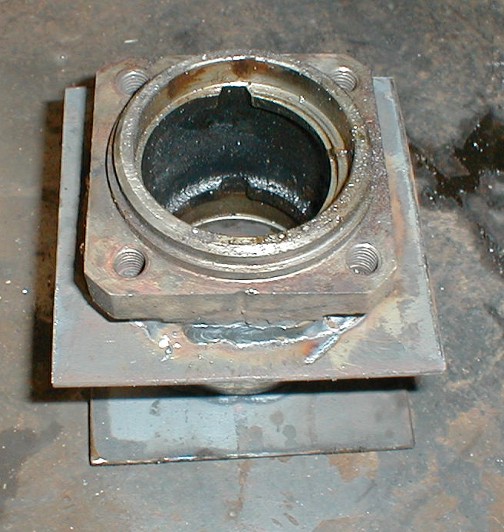
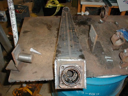
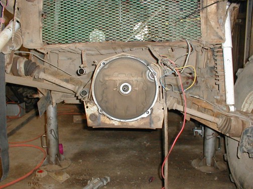
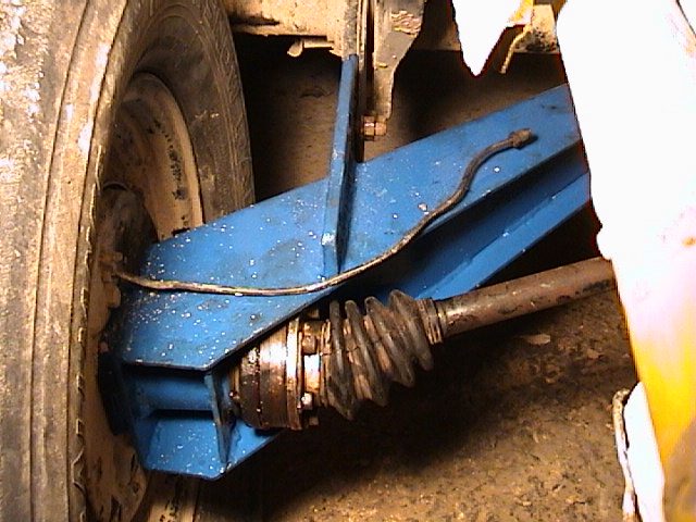
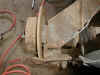
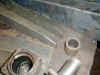
After checking the alignment of the jig, start cutting out your bearing carrier. You will need to remove all of the 11 guage (thinner) steel until you end up with just the carrier tube.
The bearing carrier then bolts on to the bearing retainer welded to the angle then welded to the surface. This holds the carrier in place. If this is not parallel to the springplate your wheel will point in the wrong direction.
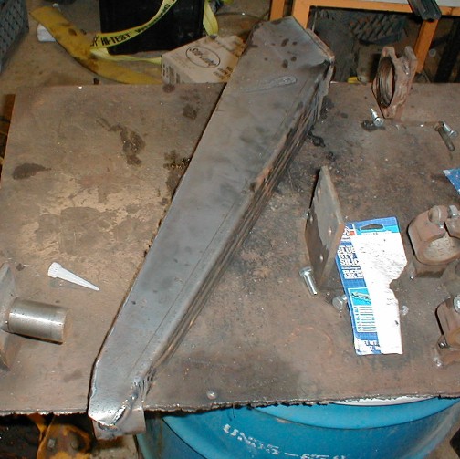
At this point the rest is putting everything on the jig and welding it up. There is some adjustment (hammer time) needed at the front of the arm and around the bearing carrier. Weld the mount for the bearing carrier first, then tack the arm to the bearing carrier and the front mount tube. Weld it all up then add the rest of the capping pieces. Last put in the
spring plate mount and weld it to the arm. Make sure that one arm has the shock mount on the top and one has the shock mount on the bottom.

After all that, you will still need to figure out your top mounts for your shocks. The cheapest set up that I am running uses a
Chevy truck coil over shock, and two KYB long travel shocks - that extend up through my fender wells and connect to my roll cage.
Keep in mind however, that I am running a turbo T-bird, full bodied bug, so
required spring rates will vary. I will say that I have not been able to turn up the spring tension enough to be able to eliminate the coil over. The leverage on the torsion rod is
just too great. Be careful about your shock mounts as they could be a serious travel limiter, if you are stopping suspension travel with your shocks. I am getting about twelve to fourteen inches of travel.
Also for the best ride, make sure you allow at least four inches of droop in your travel. I am running about six and the ride is great.
I could go on and on about all of this but I think I will stop now. Let me know if you have any questions.
Kits
and completed arms are available. Click here
for more info.
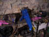
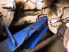
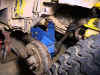
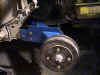
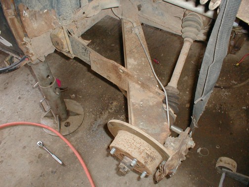
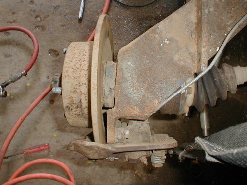
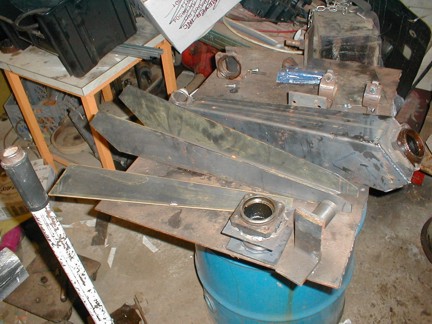
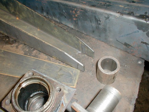
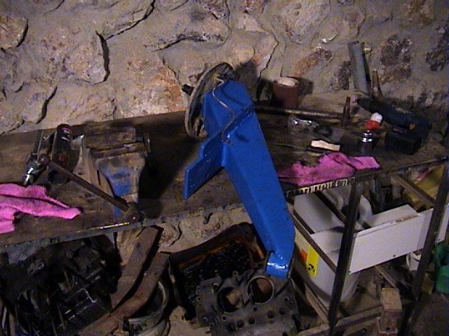
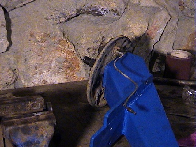
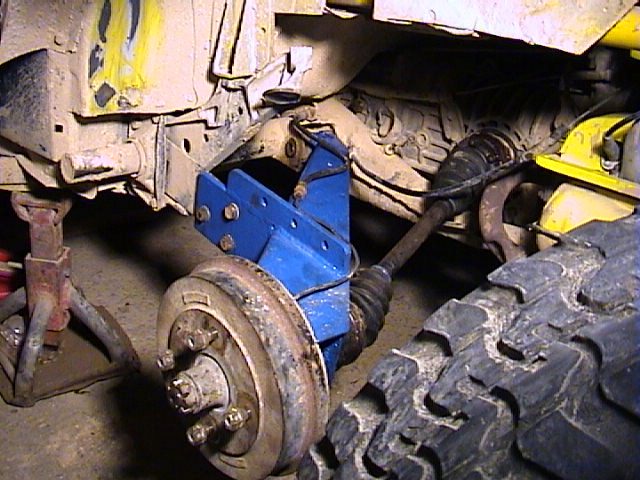
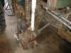
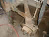
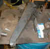
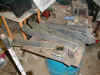
Here are some pics of some arms that Yossi over in Israel made from the
new design. He did his a little different as he welded the boxing plate
inside the arm rather than flush with the edge. It also looks as though he
used thicker material than we did.